Here are ten simple electric circuits commonly found around the home. Most of electrical symbols can change their appearance style and color according to the requirement.
 Electrical And Electronic Drawing Industrial Controls
 These diagrams show the actual location of parts color of wires and how they are connected.

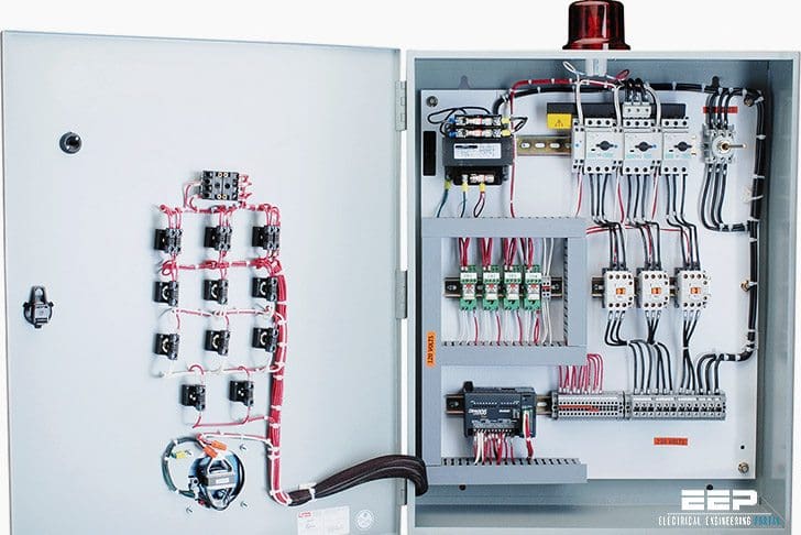
Industrial electrical circuit diagram. A photograph of an industrial controls cabinet is shown in figure 4. You should know how to isolate electric supplies and how to work safely on electrical circuits. This type of diagram is like taking a photograph of the parts and wires all connected up.
Many problems encountered in service work are electrical problems or related to electrical problems. Drawing electrical circuit diagrams you will need to represent various electrical and electronic devices such as batteries wires resistors and transistors as pictograms called electrical symbols. When including a plc in the ladder diagram still remains.
Industrial control wiring guide second edition bob mercer oxford auckland boston johannesburg melbourne new delhi. An electric circuit is a closed loop with a continuous flow of electric current from the power supply to the load. Many people can read and understand schematics known as label or line diagrams.
The standard electrical symbols are smart industrial standard and vector based for electrical schematic diagrams. Electrical cad software for automation. Electrical wiring diagrams of a plc panel.
Ac current is produced by all electric utilities. The following are examples of the fault finding training rigs where candidates diagnose faults in the control and load circuits of industrial electrical circuits the tools that the candidates use on the electrical maintenance skills course for terminating cables the training rig used for exploring the effects of short circuits overloads. A diagram that uses lines to represent the wires and symbols to represent components.
A diagram that represents the elements of a system using abstract graphic drawings or realistic pictures. The purpose of this info tec is to help you understand the fundamentals of electrical systems. Figure 4 an industrial control cabinet with wire runs terminal strip buttons on plc panel front etc.
There are two types of electrical current in common use today. Traditionally these symbols may vary from country to country but today they are standardized. We create the electrical cad software pcschematic automation the intelligent electrical design software for electrical engineering.
Accidents know how to contact the correct person the designated first aider for help. Our software is the professional choice for drawing schematics for electrical wiring diagrams control circuit diagrams pneumatics and hydraulics. Wiring diagrams help technicians to see how the controls are wired to the system.
Industrial control wiring guide. Alternating current ac and direct current dc. Electric circuits like ac lighting circuit battery charging circuit energy meter switch circuit air conditioning circuit thermocouple circuit dc lighting circuit multimeter circuit current transformer.
But it does tend to become more complex. Electrician circuit drawings and wiring diagrams youth explore trades skills 3 pictorial diagram.
 Electrical Diagrams Phase Motor Connection Electryc And Instrumen
  Three Phase Wiring
  Schematic Wikipedia
  Electrical Circuit Diagram Of Mixer Grinder Circuit Diagrams
  Ac Motor Control Circuits Ac Electric Circuits Worksheets
  Electrical Troubleshooting Plc Troubleshooting Training
  Industrial Wiring Diagram Wiring Diagram Section
  Industrial Motor Control Diagrams Wire Management Wiring Diagram
  Electrical Wiring Control Wiring